


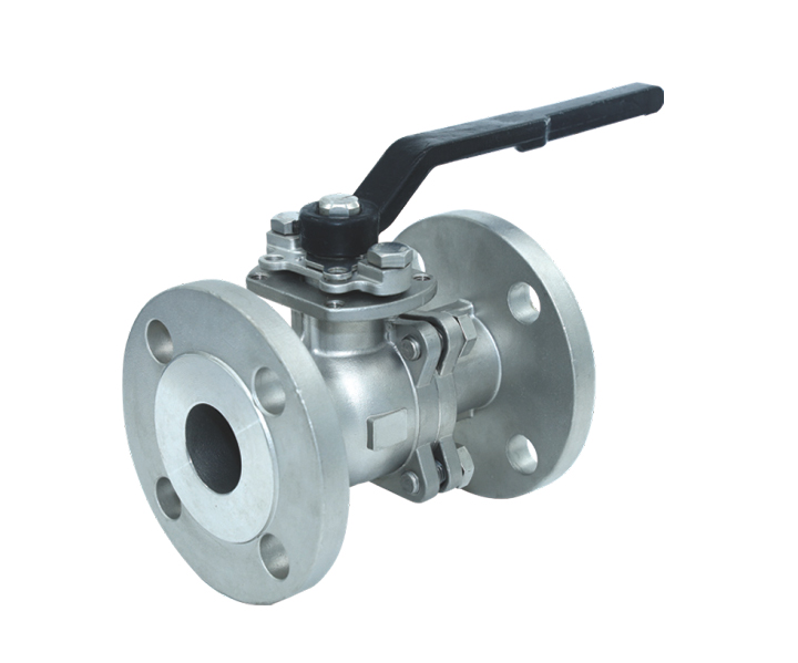


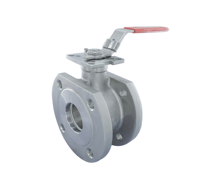
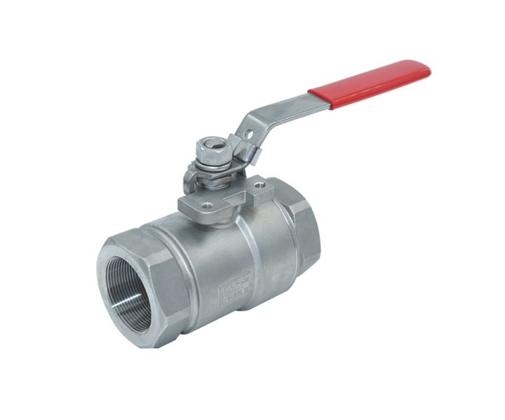
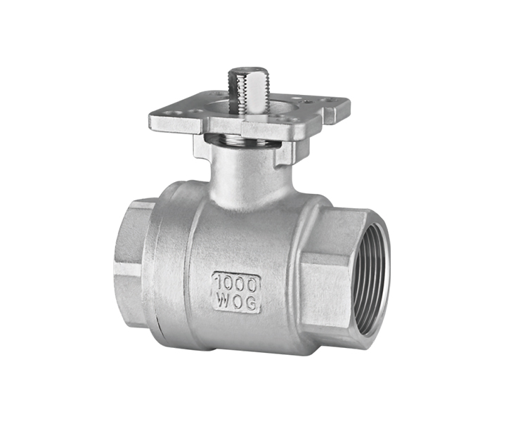
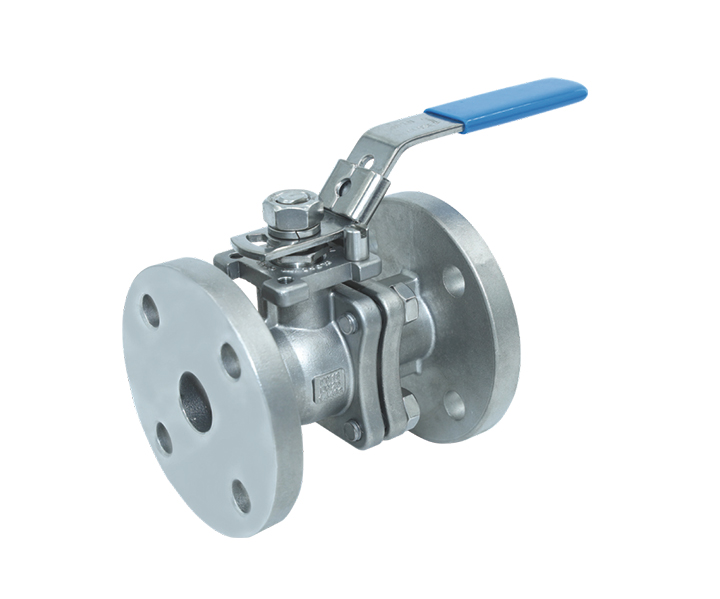
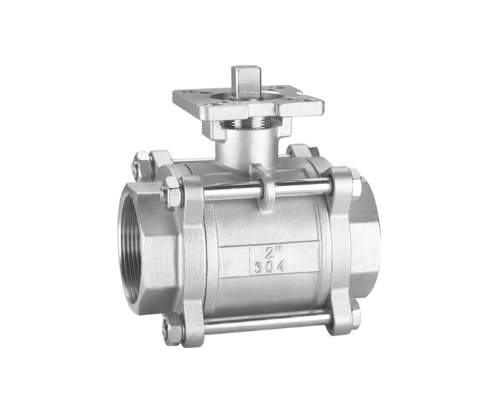
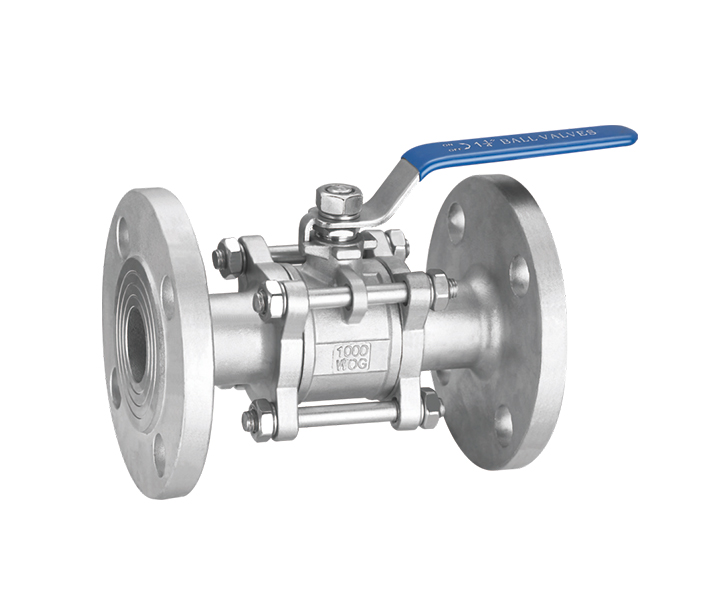
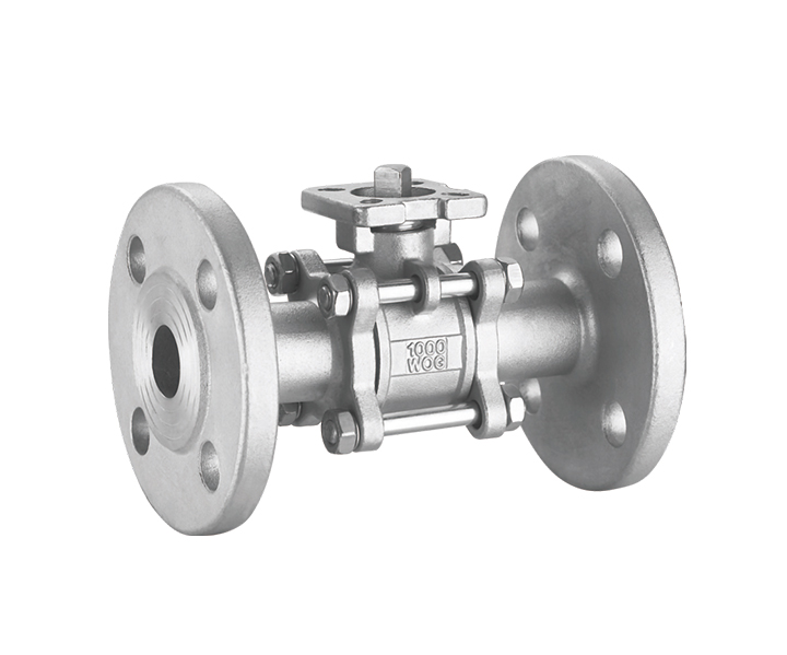
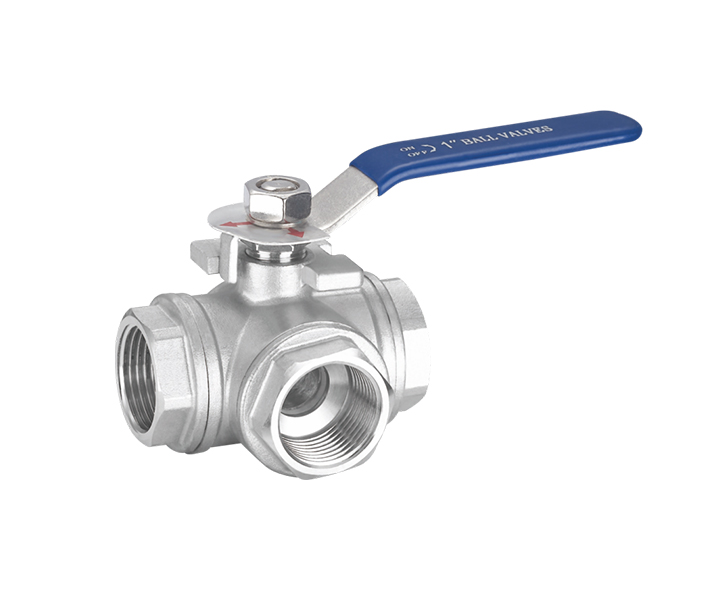
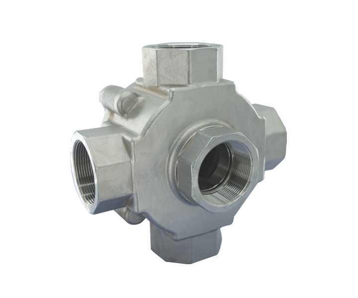
2-PC Full Port Direct Mounting Pad Flanged End Ball Valve
Product details
Design Features
1. Dewaxed precision cast body and cap
2. With fire-resistant structural design and certification
3. Built-in ISO 5211 direct mounting pad easy automation
4. Blow-out proof stem
5. Pressure balance hole in ball slot
6. Anti-static devices for ball-stem-body
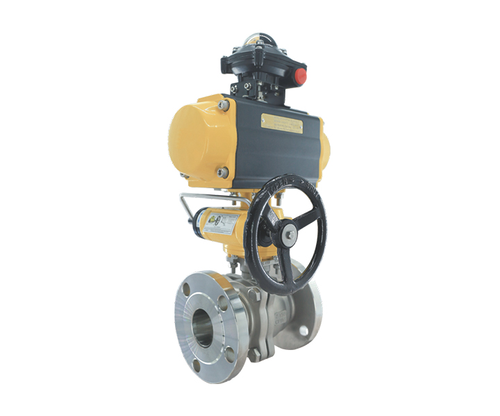
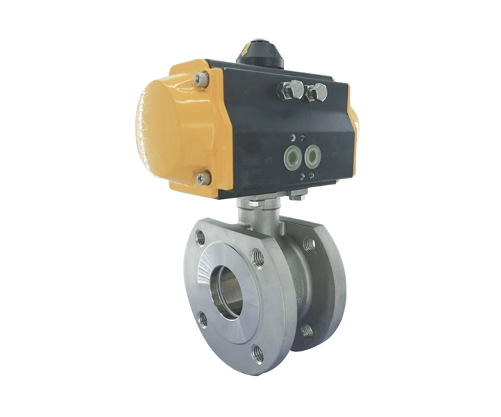
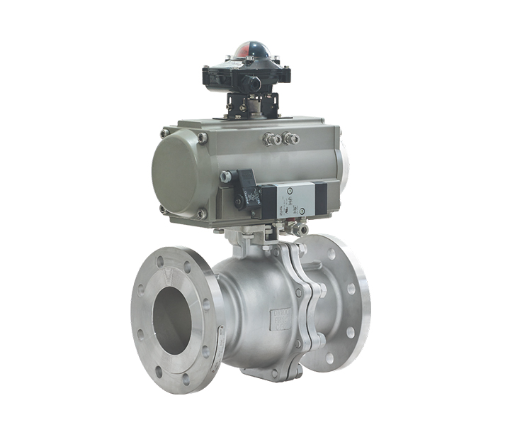
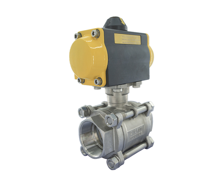
Options: (1).Actuator,(2).Limit switch,(3).Positioner
Applicable Standards
1. Design standard : APl 608,ASME B 16.34, JIS B200 1, EN 12516-1
2. Frie safe : APl 607,ISO 10497
3. Face to face: ASME B 16.10,JIS B2002, EN 558-27-1
4. Flanged ends : ASME B 16.5 , JIS B2220, EN 1092-1
5. Wall thickness : ASME B 16.34 , EN 125 16-1
lnspection & testing : APl 598,APl 6D, JIS B2003 , DIN 3230/3, EN 12266- 1
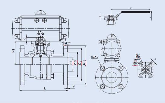
Dimension Parameter (ASME CLASS 150) Unit:mm
|
NPS |
d |
L |
H |
H1 |
W |
G |
C |
D |
tf |
f |
N-ΦK |
P |
X |
A |
a |
B |
b |
ISO5211 |
|
|
Table 8 |
Table 9 |
||||||||||||||||||
|
1/2" |
15 |
108 |
89 |
49 |
113 |
35.1 |
60.5 |
89 |
9.7 |
7.9 |
1.5 |
4-Φ16.0 |
9 |
9 |
42 |
6 |
36 |
6 |
F03,F04 |
|
3/4" |
20 |
117 |
91 |
52 |
113 |
42.9 |
69.8 |
99 |
11.2 |
8.6 |
1.5 |
4-Φ16.0 |
9 |
9 |
42 |
6 |
36 |
6 |
F03,F04 |
|
1" |
25 |
127 |
105 |
64 |
188 |
50.8 |
79.2 |
108 |
12.7 |
9.7 |
1.5 |
4-Φ16.0 |
11 |
11 |
50 |
7 |
42 |
6 |
F04,F05 |
|
11/4" |
32 |
140 |
113 |
71.5 |
188 |
63.5 |
88.9 |
117 |
14.2 |
11.2 |
1.5 |
4-Φ16.0 |
11 |
11 |
50 |
7 |
42 |
6 |
F04,F05 |
|
11/2" |
40 |
165 |
120 |
79 |
200 |
73.0 |
98.6 |
127 |
15.9 |
12.7 |
1.5 |
4-Φ16.0 |
14 |
14 |
70 |
9 |
50 |
7 |
F05,F07 |
|
2" |
50 |
178 |
128 |
87 |
200 |
91.9 |
120.6 |
152 |
17.5 |
14.2 |
1.5 |
4-Φ19.1 |
14 |
14 |
70 |
9 |
50 |
7 |
F05,F07 |
|
21/2" |
65 |
190 |
155 |
110 |
273 |
104.6 |
139.7 |
178 |
20.6 |
15.7 |
1.5 |
4-Φ19.1 |
17 |
17 |
102 |
11 |
70 |
9 |
F07,F10 |
|
3" |
80 |
203 |
165 |
121 |
273 |
127.0 |
152.4 |
190 |
22.4 |
17.5 |
1.5 |
4-Φ19.1 |
17 |
17 |
102 |
11 |
70 |
9 |
F07,F10 |
|
4" |
100 |
229 |
187 |
140 |
292 |
157.2 |
190.5 |
229 |
22.4 |
22.4 |
1.5 |
8-Φ19.1 |
22 |
22 |
102 |
11 |
70 |
9 |
F07,F10 |
Dimension Parameter (ASME CLASS 300) Unit:mm
|
NPS |
d |
L |
H |
H1 |
W |
G |
C |
D |
tf |
f |
N-ΦK |
P |
X |
A |
a |
B |
b |
ISO5211 |
|
1/2" |
15 |
140 |
89 |
49 |
113 |
35.1 |
66.5 |
95 |
12.7 |
1.5 |
4-Φ16.0 |
9 |
9 |
42 |
6 |
36 |
6 |
F03,F04 |
|
3/4" |
20 |
152 |
99 |
59.5 |
113 |
42.9 |
82.6 |
117 |
14.2 |
1.5 |
4-Φ19.1 |
9 |
9 |
42 |
6 |
36 |
6 |
F03,F04 |
|
1" |
25 |
165 |
105 |
64 |
188 |
50.8 |
88.9 |
124 |
15.7 |
1.5 |
4-Φ19.1 |
11 |
11 |
50 |
7 |
42 |
6 |
F04,F05 |
|
11/4" |
32 |
178 |
113 |
71.5 |
188 |
63.5 |
98.6 |
133 |
17.5 |
1.5 |
4-Φ19.1 |
11 |
11 |
50 |
7 |
42 |
6 |
F04,F05 |
|
11/2" |
40 |
190 |
120 |
79 |
200 |
73.0 |
114.3 |
155 |
19.0 |
1.5 |
4-Φ22.2 |
14 |
14 |
70 |
9 |
50 |
7 |
F05,F07 |
|
2" |
50 |
216 |
128 |
87 |
200 |
91.9 |
127.0 |
165 |
20.6 |
1.5 |
8-Φ19.1 |
14 |
14 |
70 |
9 |
50 |
7 |
F05,F07 |
|
21/2" |
65 |
241 |
155 |
110 |
273 |
104.6 |
149.4 |
190 |
23.9 |
1.5 |
8-Φ22.2 |
17 |
17 |
102 |
11 |
70 |
9 |
F07,F10 |
|
3" |
80 |
282 |
165 |
121 |
273 |
127.0 |
168.1 |
210 |
26.9 |
1.5 |
8-Φ22.2 |
17 |
17 |
102 |
11 |
70 |
9 |
F07,F10 |
|
4" |
100 |
305 |
187 |
140 |
292 |
157.2 |
200.2 |
254 |
30.2 |
1.5 |
8-Φ22.2 |
22 |
22 |
102 |
11 |
70 |
9 |
F07,F10 |


 View mobile website